Step7 组态PC Station 与 S7-1200 CM1243-5 基于Profibus 的S7 通信
硬件:
CPU1214C DC/DC/DC,V2.2
CM1243-5
CP5611 A2
软件:
STEP 7 V5.5
SIMATIC NET V8.2
STEP7 V11 SP2 Update5
由于CM1243-5 支持S7通信,因此,可以使用SIMATIC NET 组态的OPC 服务器与其建立S7通信连接。
操作步骤
1、使用 STEP7 V11 生成 S7-1200 项目文件
通过“添加新设备”组态 S7-1200 站PLC_1,选择 CPU1214C DC/DC/DC V2.2 创建项目。 如图1所示。
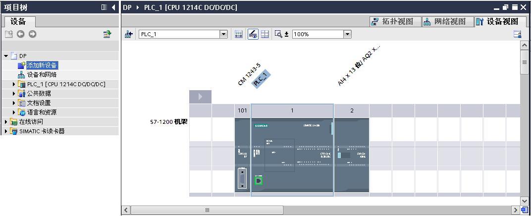
图1 创建 S7-1200 项目文件
组态 CM1243-5 ,为 CM1243-5 添加子网PROFIBUS _1,分配站地址为2 。 如图2 所示。
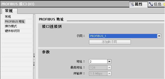
图2 组态 CM1243-5
点击添加新块,生成块访问方式为“标准-与S7-300/400兼容”模式全局块数据块 DB1。如图3 所示。
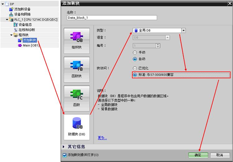
图3 创建DB块
双击 DB 1,添加数据元素 data,数组数据类型, 1000个字节,编译 DB 1。如图4所示。
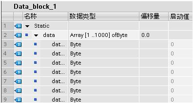
图4 创建DB块元素
编译PLC_1站,下载到 CPU。
2、用STEP 7 组态SIMATIC PC Station
(1)打开STEP7 V5.5 生成新项目CM1243-5,在项目中添加SIMATIC PC Station。
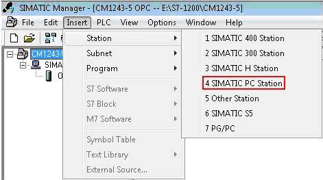
图5 建立PC站
双击Configuration进入PC站的硬件组态。
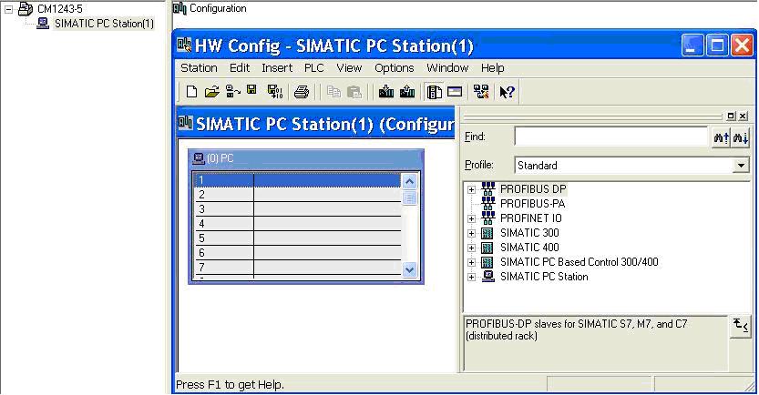
图6 进入硬件组态
添加OPC Server。
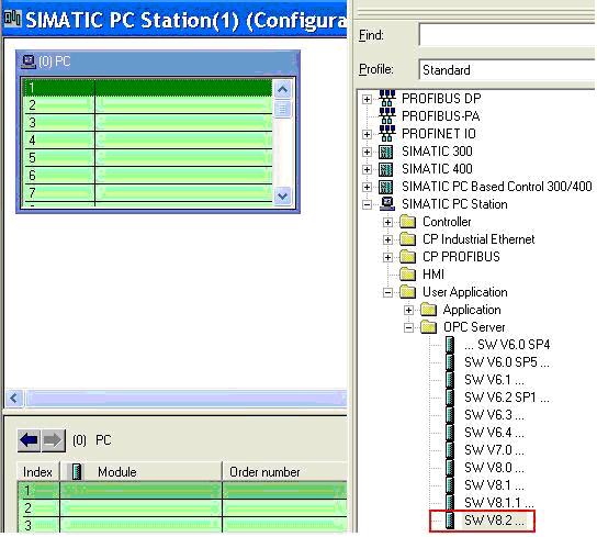
图7 添加OPC Server
添加CP5611 ,为CP5611添加新网PROFIBUS(1),并选择地址为0,编译存盘。
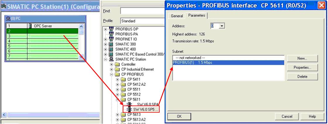
图8 添加CP卡
(2)组态网络连接
双击 进入网络组态,点亮OPC Server,在连接编辑栏右键插入新的连接,建立一个连接对象为 Unspecified 的 S7 Connection,点击 OK 确认连接。
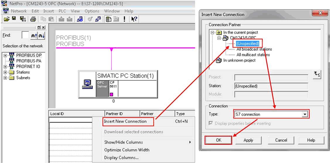
图9 建立S7连接
双击连接组态连接参数。在General中选择连接伙伴的PROFIBUS 地址为2,点击Address Details 定义连接伙伴 S7-1200 CPU 的 TSAP(03 00和03 01都可以)。
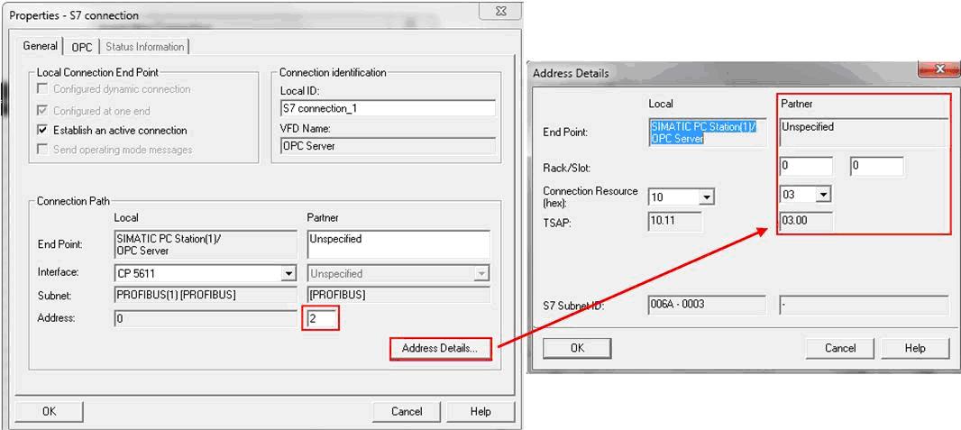
图10 修改参数
点击 OPC Server 站右键选择 Object Properties,在接下来的对话框中的 Configuration 选择生产.xdb 文件的路径,默认路径为项目文件的目录XDBs。
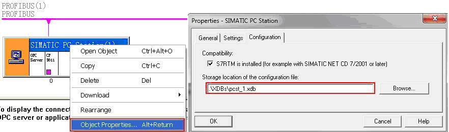
图11 设置XDB路径
(3)导入组态到 OPC Server
双击“Station Configurator”进入“Station Configuration Editor”,点击“Import Station” 导入(2)中生成的文件“pcst_1.xdb”。
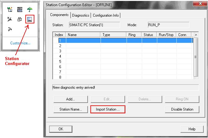
图12 导入XDB文件
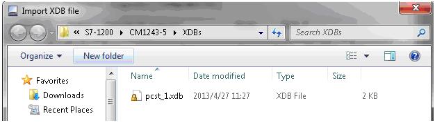
图13 浏览到XDB文件
组态正确导入后,连接建立。
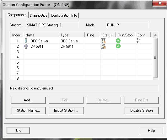
图14 导入完成
3、检查通信连接
计算机开始菜单,执 行SIMATIC NET的 OPC Scout V10 打开“Server Explorer”。
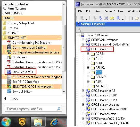
图15 打开OPC Scout
打开“S7”中“S7 connection_1”的“objects”,添加变量,将添加的变量拖入到 “DA view”,点击“Monitoring ON ”查看变量状态。
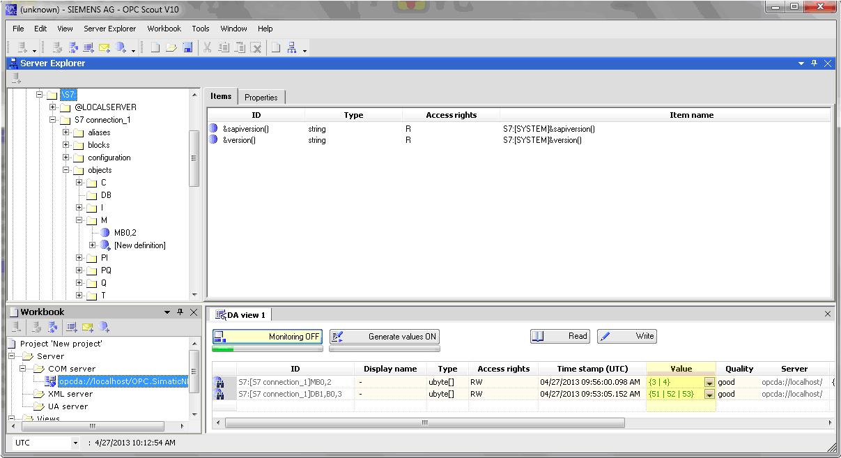
图16 监视变量
打开 PLC 变量表比较变量的值。
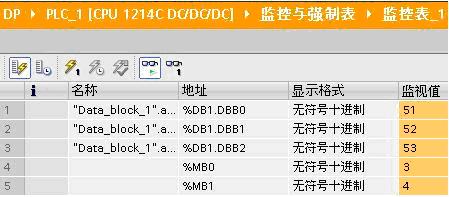
图17 监视DB


 西门子官方商城


扫码分享